Speaker
Description
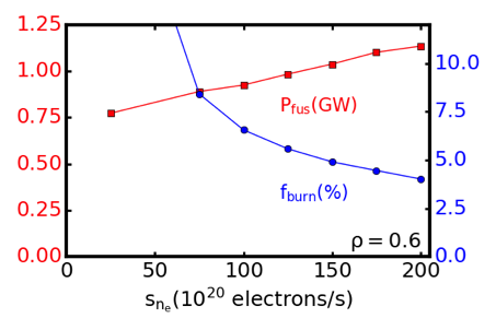
Accurate modeling of integrated core-pedestal solutions with self-consistent and validated fueling source is critical to the assessment and optimization of fusion performance and the tritium burn fraction in ITER and other future burning tokamak devices. Self-consistent modeling using the stability, transport, equilibrium, and pedestal (STEP) workflow in the OMFIT integrated modeling framework suggests future devices such as ITER and CFETR will benefit from high-density operation (Greenwald limit fraction $f_{gw}\sim$ 0.7-1.3). Regimes with operational density near the Greenwald limit will likely need peaked density profiles so that the pedestal density remains below the Greenwald limit. Peaked density profiles can be achieved with the help of pellet injection. One STEP workflow iterates between predicting pedestal with EPED, core profiles with TGYRO (TGLF+NEO), current profile with ONETWO, and EFIT for equilibrium, and provides a useful tool for integrated modeling for steady-state transport. This workflow is applied to DIII-D and EAST tokamaks and finds good agreement with the experiments. As shown in Fig. 1, on DIII-D the STEP workflow has simulated confinement from a pellet fueling discharge finding reasonable agreement with the experiment. On ITER the effect of pellet fueling is examined on two high-density scenarios: a 15 MA super-H mode inductive scenario and a 12 MA advanced inductive scenario. A fusion gain of $Q = 9 – 13$ is predicted with strong central pellet fueling. On CFETR, as illustrated in Fig. 2, the predicted fusion power and tritium burn-up fraction are $P_{fus}$ = 1 GW and $f_{burn} \sim 5\%$ when a central pellet fueling rate of $1.5 \times 10^{22}$ electrons/s is added to the STEP workflow.
A comprehensive Pellet Ablation Module (PAM) has been developed for transport studies of pellet fueling and incorporated in the STEP workflow under OMFIT. The Pellet ablation rate is based on analytical Parks’ ablation model for homogeneous DT mixtures$^1$, modified by the magnetic-field dependence based on 2D simulations of neon pellets$^3$ with the ablation rate scaled like $B_t^{-0.843}$. PAM has been developed for transport studies of pellet fueling and has been incorporated in the STEP workflow. The module supports arbitrary injection angles, general geometry injection, multiple-layer pellets such as dispersive-shell pellets, finite areal pellet deposition, and magnetic field dependence to pellet ablation. Experimental comparisons are needed to validate these dependencies.
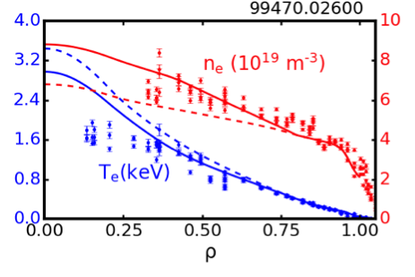
The STEP workflow with pellet fueling has been tested against DIII-D pellet-fueling experiments, and finds reasonable agreement. Fig. 1 shows a comparison with a DIII-D L-mode discharge 99470 with core pellet fueling from 1800ms to 3200 ms. The separatrix boundary, NBI heating power, and large radius ($\rho>0.8$) $T_e$ and $n_e$ are matched to the experiment. Then the workflow is performed with and without an averaged 4 Hz low-field side injected pellet source with velocity 570 m/s and radius 1.4 mm to represent an approximate average pellet fueling in the discharge. The addition of the pellet source increases $n_e$ and lowers Te with only a small change to the total $\beta$, consistent with the experiment. The Thomson scattering measurements of $n_e$ and $T_e$ are also shown for discharge 99470 after the initial transient phase in $n_e$ from the pellet fueling at 2600 ms. The values of $n_e$ and $T_e$ match well from $\rho = 0.4-0.8$. However, there is an over-prediction in $T_e$. This over-prediction may be due to the assumption of fast-ions classically heating the plasma. PAM predictions of deep shell-pellet deposition with a thin carbon shell are also consistent with DIII-D shell-pellet experiments$^{3}$.
The predicted performance of CFETR improves significantly when a pellet-like Gaussian-shape core density fueling source is incorporated into the STEP workflow. One of the critical missions for CFETR is to breed more tritium than is consumed by the device. A tritium burn-up rate of at least 3\% is required to meet this objective. Fig. 2 shows the predicted fusion power ($P_fus$) and tritium burn-up rate ($f_{burn}$) for a CFETR H-mode scenario. As the density fueling is increased, the predicted fusion power increases and is predicted to meet the CFETR goal of 1 GW fusion power when $1.5 \times 10^{22}$ $m^{-3}$ electron/s are added. Variation of the radial location of the density source have been performed finding that predicted $P_{fus}$ and $f_{burn}$ increases with increased fueling depth, suggesting that deep fueling penetration is key to high performance. In order to achieve this fueling depth with pellets, shell pellets are likely required. To achieve deep fueling, one possibility is to encapsulate the frozen fuel inside a thin shell of low-Z material. PAM predicts that a pellet with a 0.2 mm diamond shell injected from the low field side with velocity 2000 m/s can penetrate to $\rho = 0.5$ in CFETR.
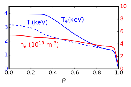
The STEP workflow is also being applied to various other tokamak devices, including EAST and HL-2M. As an example, a RF only H-mode scenario for the HL-2M tokamak has been predicted using the STEP workflow. This scenario uses auxiliary power of 2 MW of 140 GHz from the upper launcher and 2 MW of 105 GHz from the radial launcher$^{4}$. Fig. 3 shows the predicted profiles from STEP modeling. The scenario is predicted to have $\beta_N=1.25$ with $T_i$ <$T_e$ due to ECH only heating the electrons.
This material is based upon work supported by the U.S. Department of Energy, Office
of Science, Office of Fusion Energy Sciences, under Awards: DE-FG02-95ER54309 (GA Theory Grant), DE-FC02-04ER54698 (DIII-D), and GA CFETR and SWIP collaboration contracts.
(1) P.B. Parks, Theory and Simulation of Disruptions Workshop, PPPL, 17-19 July 2017, to be submitted to Phys Plasma 2020.
(2) N. Bosviel et al., 46th EPS Conference on Plasma Physics, Milan, Italy July 8-12, 2019; P1.1102.
(3) E. Hollmann, et, al., Phys. Rev. Lett. 122, 065001 (2019)
(4) L. Xue, et. Al., Nucl. Fusion 59, 016016 (2020).
| Affiliation | General Atomics |
|---|---|
| Country or International Organization | United States |