Speaker
Description
-
INTRODUCTION
The super-X divertor (SXD) configuration features larger plasma wetted area than conventional SN divertor, due to large $R_{target}$. The wetted area is further increased with the longer connection length, which allows more time for cross-field transports. Other main features of SXD include baffling and large outer divertor volume. This means potentially higher maximum radiated power in the divertor. In scanning the heating power, fuelling and impurity seeding rate in simulations for DEMO, we found a wide operation window in SXD configuration both at designed value of $P_{SOL}=150MW$ and at a higher value of $P_{SOL}=250MW$. The current SXD configuration for DEMO has $L_{\parallel,it}/L_{\parallel,ot}\approx1.25$ at $3mm$ radial distrance from the separatrix at the outer board midplane, smaller than that in SN which is $L_{\parallel,it}/L_{\parallel,ot}\approx1.8$. According to the 2-point model [1 ], the power distribution between the inner and outer divertor should be more symmetric in SXD. However, we observed deviation from the model prediction for the SXD, measuring large asymmetry between the two divertors with either the inner or the outer divertor receiving larger share of the $P_{SOL}$, depending on the plasma condition in the two regions. -
OPERATION WINDOW IN SXD CONFIGURATION IN DEMO
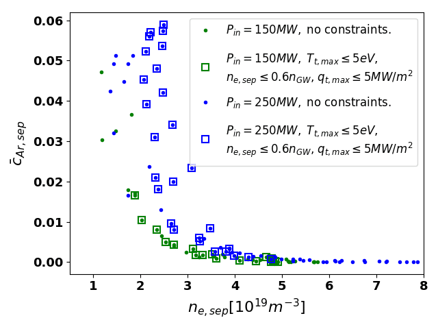
The simulation shows that the operation window, defined by applying constraints of $T_t\leq5eV, q_{\perp t}\leq5MW/m^2$ and $n_{e,sep}\leq0.6n_{GW}$, obtained in the fuelling rate, argon seeding and heating power scans is wide in SXD. This is manifested in Fig. 1 in the 'separatrix density $-$ impurity concentration' frame. We see that $n_{e,sep}$ decreases as a function of $\bar{c}_{Ar,sep}$, with the spanning of $n_{e,sep}$ being more than 2 folds and $\bar{c}_{Ar,sep}$ varying from trace level to as high as $6\%$. Later we may also need to put constraint on $\bar{c}_{Ar,sep}$ to regulate argon radiation in the confined region as well as its enrichment in the divertor. Another encouraging result suggested by the simulation is that the argon enrichment in the divertor reached 3.0 within the operating window, partly as a result of plasma flow pattern changing, which itself is affected by the ionization sources in the inner and outer divertors.
-
EFFECTS OF IMPURITY SEEDING ON THE MAIN PLASMA DENSITY
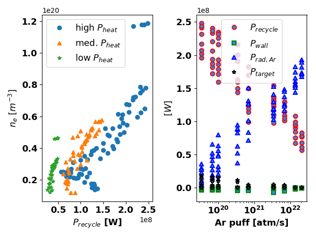
From Fig. 1, one notices that as the impurity concentration ${c}_{Ar}$ increases, the $n_{e,sep}$ decreases. Since this could be important in, e.g. feedback control of detachment via power dissipating through impurity radiation, we investigated this phenomenon. We found that this density drop is strongly correlated with the power available for deuterium recycling $P_{recycle}$, as is shown in Fig. 2 (left). $n_e$ goes down almost linearly with decreasing $P_{recyle}$. Moreover, it shows that the density drop is more profound at high $P_{heat}$ (reactor level), and milder at low $P_{heat}$ (close to current machine level). The observation of density drop during impurity seeding is also consistent with the observations in some JET experiments, as reported in [2 ]. Fig. 2 (right) reveals that $P_{recyle}$ decreases primarily with argon seeding, as a result of increased power radiated away by the impurity. We also saw that the electron static pressure $p_{e,sep}$ decreases together with the $n_{e,sep}$. The simulation shows that $p_{e,target}/P_{recycle}$ decreases with $T_{et}$, while $P_{recycle}$ increases with the temperature. This suggests that the loss of upstream pressure might be due to the decrease of $p_{e,target}$ with seeding and the lack of enough plasma momentum removed along the flux tube.

-
INNER/OUTER DIVERTOR ASYMMETRY
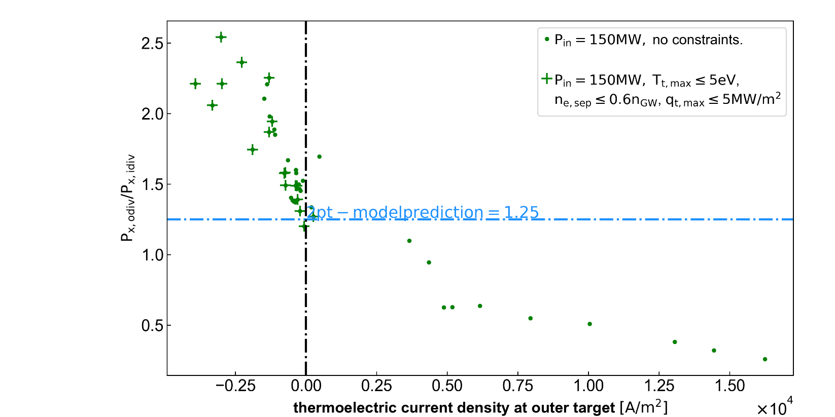
One asymmetry we observed is the power into the inner and outer divertor at the divertor entrances. As mentioned before, the power distribution in the simulation between the two divertor regions, represented by the raio $P_{x,odiv}/P_{x,idiv}$ , departed from the 2-point model predictions. We can see in Fig. 3 that the ratio varies between 0.3, which corresponds to more power into the inner divertor, and 2.5, meaning more to outer divertor. Fig. 3 demonstrates that this asymmetry in power distribution is correlated with the thermoelectric current flowing between the inner and outer targets. More power goes into the outer divertor when the current directs from the outer to the inner target, and more to the inner divertor when it reversed direction. The thermoelectric current arose as a result of the $T_e$ difference at the two targets [3 ]. This current has two ways of contributing to the asymmetric power distribution: 1) the electron current which is in the opposite direction of the thermoelectric current carries heat with it. 2) the thermoelectric current induces a net convective electron heat flux in the opposite direction. The other thing we noticed is that, in the SXD configuration, for the DEMO plasma to be within the operating window, more share of $P_{SOL}$ needs to go to the outer divertor, as is indicated by Fig. 3 where cases within the operating window crowed exclusively in the in the region where $P_{x,odiv}/P_{x,idiv} \geq 1.25$ and theremoelectric current transports heat into the outer divertor. We also observed that the impurity radiation in the outer divertor can reach 2 folds of that in the inner divertor. The impurity concentration or the enrichment is higher in the outer divertor as well.

-
REFERENCES
[1 ] C S Pitcher and P C Stangeby 1997 Plasma Phys. Control. Fusion39 779
[2 ] L Aho-Mantila et al, Journal of Nuclear Materials 438 (2013) S321–S325
[3 ] P J Harbour, Contrib. Plasma Phys. 28 (1988) 415
| Affiliation | UK Atomic Energy Authority, Culham Center for Fusion Energy |
|---|---|
| Country or International Organization | United Kingdom |
