Speaker
Description
One of the major challenges in the realization of a fusion power reactor is the long-term operation of the in-vessel components and material joints under high flux 14.1 MeV neutron environment under high heat loads. This requires development of radiation resistant materials and joints and their validation under reactor relevant conditions [ 1]. At present, there exists no fusion relevant test facility that can simulate the simultaneous heat and the neutron loads that a component will be exposed in a reactor. Therefore, the validation of these components is carried out separately, i.e., testing under cycling loading conditions before and after exposing to specific neutron flux which is capable of producing a certain amount of dpa. The material failure is thus estimated under different loading conditions such as strain rate, temperature, dpa formed under low energy neutron irradiations (~3 MeV) etc. The failure data obtained from these studies needs to be validated for fusion conditions. This requires extensive modelling coupled with benchmark experiments. In this paper, the fatigue failure of two materials, (1) Indian Reduced Activation Ferritic Martensitic (IN-RAFM) steel and (2) SS-304, are analyzed using simulations with different neutron loads and are bench marked with fatigue analysis experiments for 0 dpa scenario (un-irradiated). The IN-RAFM is an indigenously developed steel for ITER-blanket and the composition can be found in Ref [ 2]. The SS-304 is used as weldment material for cryostat sector plates and neutral beam duct in ITER [ 3,4].
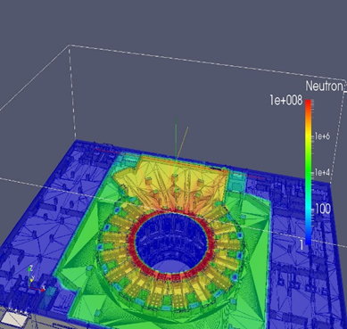
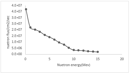
In the case of SS-304, the neutron induced dpa under ITER-like conditions under cryostat is calculated by considering the neutron flux calculated using Paraview software [ 5]. The geometry along with the neutron flux at the cryostat locations, between lower and upper cylinder, are calculated using Paraview software and is shown in Fig. 1. The neutron flux expected at NBI duct is 28 x 107cm-2 S-1 and at the seam location of cryostat is 2.28 x 107cm-2 S-1 [ 6]. A representative neutron spectrum is shown in Fig. 2. The calculated dpa values of 56Fe for ITER Safety Assessment 2 (SA2) scenario [ 7] (2.65 x10⁻¹³) [ 8] is shown in Table. 1.
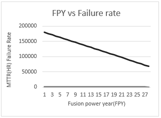
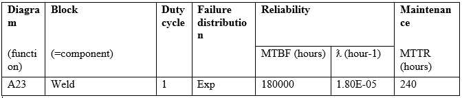
The failure analysis is carried out by using Failure Mode Effect Analysis (FMEA) which is a standard engineering practice to assess the safety and reliability of materials [ 9]. FMEA uses a block diagram approach (Blocksim) where the system is divided into subsystems and each subsystem contributes to the main with a relationship (series or parallel) by using a Reliability Block Diagram (RBD) approach. The functional breakdown of the subsystems is linked hierarchically by a reliability relation and the failure of the system is estimated by using inputs from different levels based on the mode of their relationship. The mean time to failure, MTTF, a parameter is used to identify the occurrence, severity and thus risk priority of particular scenario, is calculated from this analysis. The MTTF data for ITER cryostat weldment (Table. 2) is about 180,000 hrs (~20 years) which is much larger than the integrated plasma operation in ITER as assessed by SA2 scenario. This matches well with the ITER data base gives us the confidence in our estimation [ 8]. By assuming a linear decrease in the MTTF with small dpa, and by extrapolating the neutron flux for an ITER-like DEMO reactor with 2000 MW fusion power and 60% duty cycle, the MTTF of SS-304 at the same location, is shown in Fig. 5. The ITER-like dpa is attained less than 19 years and the maximum operation time of the cryostat and therefore the DEMO operation is reduced accordingly.
The IN-RAFM will be used as the structural material in the ITER test blanket module and can be a potential first wall/divertor material for future reactors. These regions receive much higher neutron flux (~ 1014 – 1017 cm2/S) than cryostat. The model calculates the failure of RAFM under cycling loading conditions at 300 K, for 0 dpa under various strain rates. It is bench marked with experimental data available for IN-RAFMS under similar conditions. It is already reported that at 0 dpa, at 300 K temperature, the material fatigue at 0.5 strain rate is expected to be around 4000 cycles [2]. The expected failure rate under neutron irradiation is calculated from the model and will be presented as a function of neutron flux for ITER as well as DEMO relevant conditions. A comparison of the failure rates with EUROFER and SS-304 under similar condition will be presented. To validate the credibility of the model predictions, at 0 dpa, experimental benchmarks is carried out for different structural and other in-vessel materials such as tungsten, CuCrZr and OFC copper and the results of these will also be reported in the contribution.
Neutron irradiation require long exposure times and experiments are often difficult. The outcome of the current analysis helps to narrow down the experimental window for specific irradiation conditions. The failure analysis requires a careful compilation, analysis and extrapolation of the existing data as well as the generation of additional data relevant for reactor conditions. Such world-wide efforts are already started for first-wall materials under irradiation conditions [1,11,12] and the outcome of the current analysis might also contribute to such efforts.
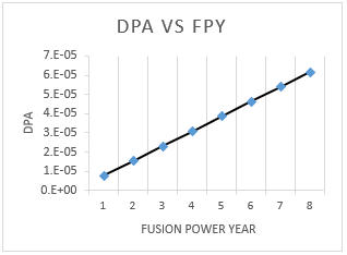
Table.1: DPA values for Fe 56+ for ITER SA2 Scenario
DPA per sec for Fe
- DPA at location /sec; 2.65E-13
- DPA/1 FPY; 7.70E-06
- 10 years; 8.36E-05
- 1.325 years; 1.11E-05
- Total DPA based on ITER operation scenario; 9.46E-05
References
[ 1] M. Gorley et al., Fusion. Eng. Design (2018), 136 298
[ 2] K. Mariappan et al., Fusion. Eng. Design (2016), 104, 76
[ 3] W. J. Mills et al., Int Material Rev, (1977), 42, 45
[ 4] W. Vandermeulen et al., J. Nucl. Material (1991), 183, 57
[ 5] A. James et al., ParaView: An End-User Tool for Large Data Visualization, Visualization Handbook, Elsevier, 2005, ISBN-13: 978-0123875822.
[ 6] P. V. Subhash, et al., Fusion Science and Technology, (2015),130, 215
[ 7] M. Loughlin and N. Taylor, ITER Document Series IDM UID2V3V8G, 1 (2004).
[ 8] M. Rajput et al., Fusion Eng. and Des. (2018) 130, 114
[ 9] Suraj et al,” Fusion engineering and Design (2019) under review.
[ 10] ITER RAMI Analysis Program IDM document(28WBXD_v4.3)(2011).
[ 11] Cadwaller.L et al., Preliminary Failure Mode and effect analysis of the US DCLL Test Blanket Module- Idaho national laboratory, USA (2007).
[ 12] R.Hiwatari et al., Nucl Fusion ,vol 45,96-109 (2005).
| Affiliation | Iter-India,Institute for Plasma research,Bhat,Gandhinagar,Gujarat,India-382428. |
|---|---|
| Country or International Organization | India |
