Speaker
Description
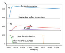
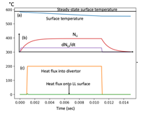
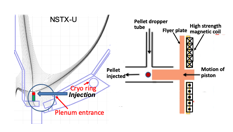
The extreme heat flux anticipated in fusion reactor divertor plasma facing components (PFCs) is perhaps the most challenging technology issue for fusion energy development. Most divertor PFCs are designed based on the maximum steady-state operational heat-flux limits of 5 – 10 MW/m$^2$. However, in addition to the steady-state heat flux, the fusion reactor divertor PFCs could also experience significant transient heat flux such as ELMs and/or other magnetic reconnection events which can deposit large transient heat flux onto the divertor PFCs. For future reactors, one might expect ~1% of plasma stored energy expulsion in an ELM or some other MHD event. Assuming a 2 GJ fusion reactor plasma stored energy, one could expect ~ 20 MJ of transient heat pulse into the divertor in a relatively short time duration of ~ 5 - 10 msec which is ~ 1 – 2 GW/m$^2$ assuming ~ 2 m$^2$ of divertor strike-point area. A conventional divertor heat flux mitigation technique such as the divertor detachment would not work for such high heat flux transient pulse. Since rapid heat removal via thermal conduction is not feasible, 20 MJ of energy deposition if impinges on a tungsten PFC surface would melt ~ 20 - 30 kg of tungsten material as shown in Fig. 1, which could significantly damage the tungsten PFC surfaces and could eventually lead to more serious issues such as a coolant leakage into the vacuum chamber. The liquid metal (LM) PFCs are more resilient against such transient heat flux as it could evaporate LM as needed and the evaporated LM can be then replenished afterward. In Fig. 2, we show a LM PFC case where the tungsten PFC surface (as in Fig. 1) is coated with 1 mm thick liquid lithium (LL). As the LL temperature rises as shown in Fig. 2, the evaporated/injected lithium also increases rapidly, due to the rise in the LL vapor pressure, as shown in Fig. 2. As the injected lithium increases, associated radiative cooling reduces the heat flux on the lithium surface as shown in Fig. 2. With the heat flux reduced, the Li surface temperature rise saturates near 900 °C as shown in Fig. 2. This example shows that the LL surface does indeed protect the tungsten substrate from melting by the high transient heat flux. One potential issue is that while the surface temperature rises rapidly to ~ 900 °C, the surface temperature only cools down slowly since there is no rapid cooling mechanism available as shown in Fig. 2. The blackbody radiation is small and the conduction cooling is slow ~ 1 sec. This slow cool down results in continuing lithium evaporation/injection even after the heat pulse is over with a decay time of ~ 500 msec as shown in Fig. 2. The prolonged lithium injection could cause undesirable effects such as excessive LL / LM injection and eventual degradation of plasma performance which could even lead to a plasma termination. A solution we propose here is a timely injection of light impurities which would just balance the transient heat flux with appropriate radiative cooling leaving the actual divertor PFCs surface temperature unchanged which would be suitable for both solid and LM PFCs. As shown in Fig. 3, the divertor PFC surface temperature rise can be prevented by the timely and controlled injection of lithium into divertor. Fig. 3 shows the PFC surface temperature actually gets slightly reduced somewhat due to heat flux reduction. This is accomplished by starting the lithium injection ~ 1-2 msec ahead of the arrival of the transient heating pulse as shown in Fig. 3. Once the heat pulse is over, the lithium injection stops and the lithium density decays with the confinement time ~ 1 msec. Accordingly, the prompt lithium injection can prevent the transient heat flux from arriving at the PFCs while the total li injection can be reduced by a factor of x5 compared to the passive LL PFC case in Fig. 2. With non-recycling light impurity injection such as lithium, beryllium, or boron, one could avoid plasma performance degradation or disruption due to excessive impurity injection. Lithium has an advantage of reducing the recycling by providing additional pumping which could improve the plasma performance (1, 2). In order to implement the active mitigation system, it is important to determine the actual lithium deposition location for maximum effectiveness. The location should be sufficiently upstream from the divertor strike point to allow volumetric radiative cooling so that the heat flux can be distributed to the entire divertor wall surfaces to facilitate the heat removal as shown in Fig. 4. Even for those events which are not predictable, as the heat pulse originates from the main plasma, since the detection of such event can be done rapidly via fast UV or visible detectors, the heat pulse arrival time lag onto the divertor PFCs may permit the timely injection of lithium prior to the main heat pulse arrival at the divertor plate. For a fusion reactor with large major radius, the warning time could be as much as 10 msec. As a candidate mitigation system, an inductive pellet injector design is shown in Fig. 4 where a flyer plate fabricated out of high-strength and high-conductivity is used. The pellets or the shell-pellet containing numerous smaller pellets would be dropped into a cylindrical chamber located in front of the plunger head. The pellet injector may be mounted at an angle to the vertical, so that the pellets rest on the surface of the piston. This is to avoid impact fracture of a shell pellet that is located some distance away from the pusher plate. Energizing the coil would result in rapid motion of the flyer plate, which would then propel the payload shell pellet or pellets at high velocities. Since the duration of the current pulse in the valve is less than 2 ms, it could, in principle be operated at frequencies much in excess of 100 Hz if rapid repetition is needed as in the case of the ELMs. A proof-of-principle experiment which can for example identify the optimum injection location can be conducted in present day devices such as NSTX-U.
*This work was supported by DoE Contract No. DE-AC02-09CH11466.
References
(1) M. Ono et al., Nucl. Fusion 53 113030 (2013)
(2) M. Ono M et al Fusion Eng. Des. 89 2838 (2014)

| Affiliation | PPPL, Princeton University |
|---|---|
| Country or International Organization | United States |
