Speaker
Description
The tokamak progress in 20th century accompanied by the replacement of their plasma-facing components (PFC) from high Z materials to low (Ref. 1). This made it possible to obtain a relatively pure (Zeff <1.5) fusion plasma. However, superconducting tokamaks of the 21th century discovered a new obstacle for fusion as limiting of the duration of the discharges (PH/S - limit 1) due to the accumulation of wall erosion products inside the discharge chamber, which finishes by disruption. As solution for steady-state tokamaks would be the removal of erosion products from the vacuum chamber during discharges or between them while maintaining PFC with small Z. It is desirable that they have a low melting point for removing them as liquid. The first candidate is Li. The purpose of T-11M research is a creation of lithium PFC protection in the form of a thin lithium film covering the wall and lithium plasma filling SOL for reducing the plasma-wall electric field and suppressing unipolar arcs (Ref. 1). For this, a lithium emitter (limiter) based on capillary porous structure (CPS) (Ref. 2), injecting lithium during discharge into plasma and the Li-collectors system in SOL between the T-11M wall and the plasma edge were used. The function of the collector is to prevent lithium withdrawal to the wall, and in the future, to remove the trapped lithium outside without violating the vacuum conditions. The Li collection is based on the fact that the ionized lithium flows along the edge magnetic surfaces. A collector crossing them becomes a limiter for this flow. Until the collector temperature exceeds 300° C, it is able to accumulate incoming lithium (Ref. 1). However, its excessive immersion into the plasma periphery with plasma current can perturb the boundary magnetic surfaces (“magnetic islands”), which will activate the undesirable transport of lithium to the wall and into the plasma. We analyze hear the various combinations of the three lithium limiters at T-11M tokamak, which were used as lithium emitters and collectors.
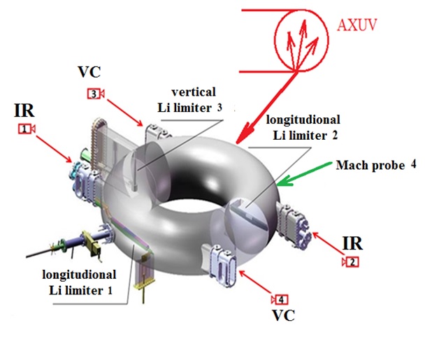
The experiments were conducted at T-11M tokamak: R/a=0.7 /0.27 m, BT = 1-1.5 T, Ip = 70-90 kA, Δt ~ 250 ms, <Ne> from 0.5 to 8 1019 m3. Figure 1 shows the scheme of T-11M with system of its movable lithium limiters: a vertical lithium CPS emitter with a operated surface coated by W-felt with lithium 2 (Figure 1, 3), and two similar longitudinal limiters (Fig. 1 1,2) using as lithium CPS-based collectors installed at a small angle to the toroidal magnetic field in the SOL region created by the vertical emitter.
To record the temperature of the longitudinal Li-collectors during the discharge, two high-speed infrared (IR) cameras (Fig.1, IR-1,2) VarioCam HD were used, which made it possible to simultaneously observe the temporal surface temperature variation of both limiters during the experiment. In visible light, two cameras (Figure 1, VC - 3 and 4) recorded their behavior. A Mach probe (figure 1, 4) was used to control the plasma parameters in SOL.
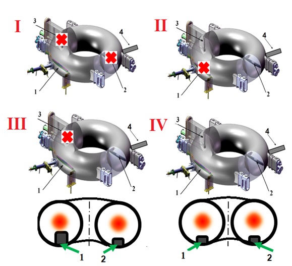
In the course of development of the T-11M limiter system, they were used as separate emitter-collector combinations. Figure 2 shows a scheme of the respective combinations.
The vertical lithium emitter (figure 1, 3) was used in two combinations II and IV as the main lithium emitter. In other cases, it was removed into the port.
The power of the heat flux P coming to the surface of the limiter during the discharge was calculated according to ΔТ(t) taking into account "grayness".
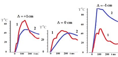
As mentioned above, the main function of the collector system is to prevent excessive lithium flux to the wall. Comparison of different schemes of lithium emitters and collectors (I-IV figure 2), showed that the best scheme with cleanest and hottest plasma was IV. Mach probe and LiI measurements revealed that scheme IV is characterized by the steepest decay λ of the lithium distribution in the SOL shadow from the hot plasma boundary to the chamber wall, which demonstrates a decrease in the radial transport of lithium in this region. Li decay λ decreased from λ=3.1cm (scheme I), λ=3cm (scheme II) and λ=3.65cm (scheme III) up to λ=1.75cm (scheme IV figure 2 ). One of the explanations of success of scheme IV could be the assumption that the asymmetry of the collectors (emitters) provides the formation of magnetic islands that destroy magnetic surfaces in limiters regions. The IR measurements confirmed the validity of this assumption. For this, an experiment was conducted with the vertical displacement of the plasma column on two symmetric lithium limiters 1 and 2 (case III ). A small (~ 1.5cm) initial vertical shift made it possible to divide them into a “lead” (1) and a “slave” (2). Under the conditions of cylindrical symmetry small shift (1cm) of the plasma column to the “lead” limiter should not qualitatively change the ratio between the heat fluxes arriving at such slightly shifted symmetric limiters (figure 2 scheme III ). It was true while the shift was small. When it reached 2cm, (figure 3 the ratio between the IR signals changed dramatically - the heat flux to the “slave” 2 times exceeded the flux to the “leading”. Figure 3 sequentially shows the dynamics of changes in heat fluxes on 1 and 2 limiters as the vertical shift increases (Δ=+1cm up to Δ -1cm) . Such transition should have been expected when a magnetic island with isolated O point and an open (symmetrically of 180 ° along the torus) X-point concentrating heat flux into this zone formed at the plasma periphery.
The conclusion that can be made on the basis of the T-11M experiments is that the local lithium emitters and collectors of the lithium circuit should be placed strictly symmetrically (with accuracy higher 1cm) radially and along the torus, thereby suppressing the possibility of the formation of magnetic islands and increased lithium escape to the tokamak walls during the creation of lithium PFC protection.
References
1.Mirnov 2019 S.V. Nucl. Fusion 59 015001
2. Evtikhin V.A. et al. 1996 16 IAEA Fusion Energy Conf. (Montreal Canada) IAEA Vienna 3 659
Figures:
| Affiliation | TRINITI |
|---|---|
| Country or International Organization | Russia |
