Speaker
Description
Jing Wu1*, Jiming Chen1, Liman Bao2, Pinghuai Wang1, Kun Wang3, Stefan Gicquel2, Xiaobo Zhu1, Qian Li1, Hui Gao1, Weishan Kang1, Rene Raffray2
1Southwestern Institute of Physics, Chengdu 610041, China
2ITER Organization, 13115 St Paul Lez Durance, France
3China Int’l Nuclear Fusion Energy Program Execution Center, Beijing 100862, China
*E-mail: wj@swip.ac.cn, Tel: +86-28-82820873
The design of the 12% first wall(FW) panels of enhanced heat flux(EHF) type which China undertakes has been largely improved for better maintainability and manufacturability. Contrasting to the old one, new design realized accessible pipe connections for non-destructive testing(NDT) between fingers and the fingers mechanically assembling to the central beam(CB). It largely reduces the number of cover plates welding to various water-coolant headers and consequently reduce the water leak risk in ITER operation. It was simplified the plasma-facing surface profile with optimized Be tile shapes. As a result, the number of welds, surface facets and Be tiles reduced by 49.5%, 10% and 14.3%, respectively. Thermal mechanical analysis has been performed, consistent results were obtained with ITER requirements.
As the in-vessel and plasma-facing components, and ITER EHF FW panels need to withstand surface heat fluxes up to 4.7MW/m2 with a thermal fatigue life of 15,000 cycles1. The old design adopted 15 mm heavy section welding joint between fingers and CB, and 178 small welding covers were also adopted for its cooling channels[2]. There were more than 507 welds excluding the large number of CuCrZr/316L(N) explosion bonding and the Be/CuCrZr diffusion bonding interfaces. Water connection among them were inside the panel, welds for the pipe connection were not accessible for NDT and repairing. It gave rise to high risk of cooling water leakage and made it difficult to replace any defective fingers after assembly. Welding deformation could hardly be controlled to the requiring FW assembly tolerances. Learning from experience of semi-prototype program, such kinds of drawbacks shall be solved.
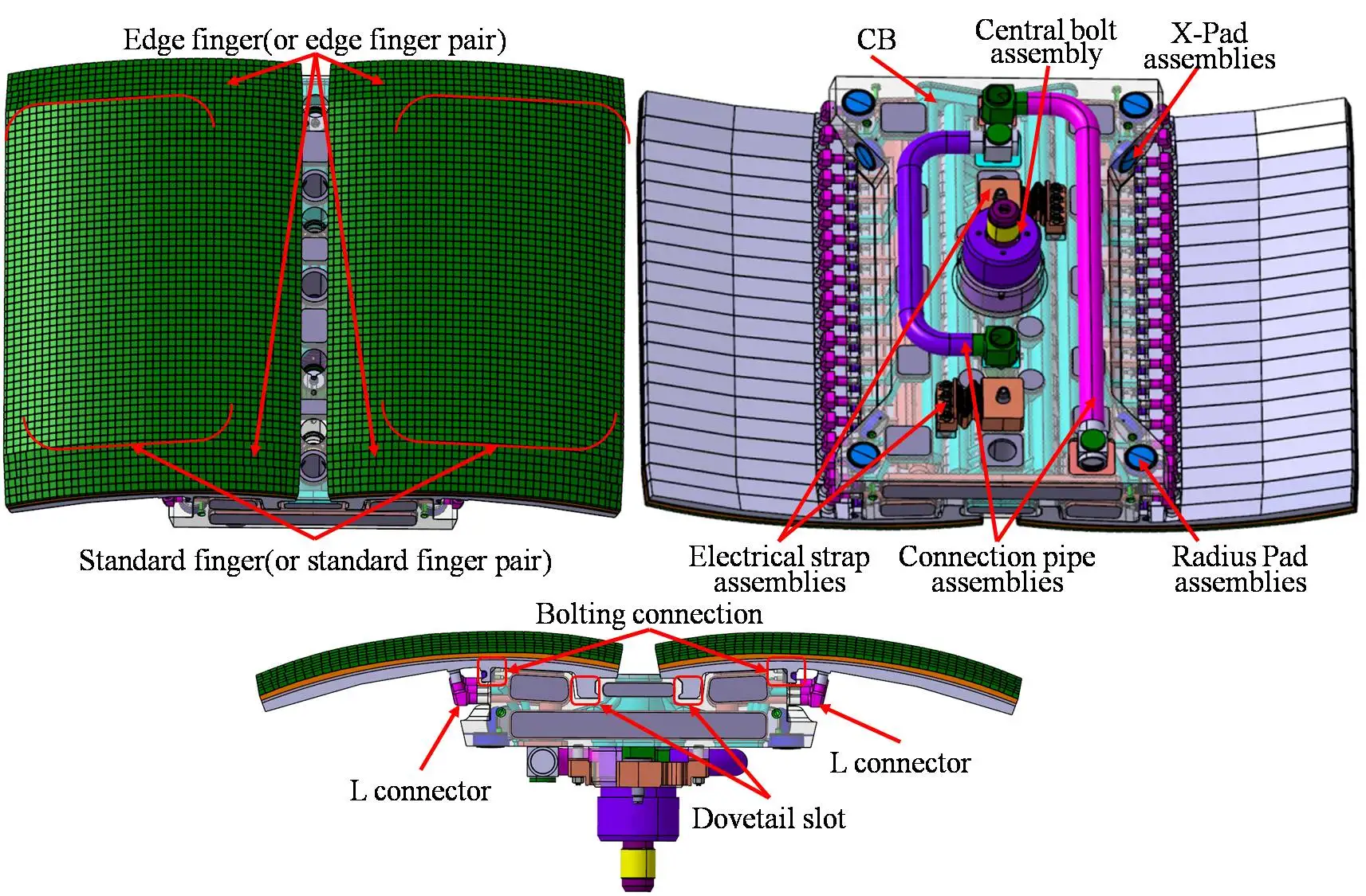
Detailed new design of an ITER EHF FW panel is shown in figure 1. It contains 32 standard fingers, 8 edge fingers and 1 CB. To conform with the magnetic field and to avoid any leading edge of unacceptable heat load, both type of the fingers have toroidal shaping but additional poloidal shaping for the edge fingers. Edge fingers have inclined Be surface in poloidal direction leading to irregular inner hypervapotron cooling channel and sharp corner profile of Be tiles. This specific design is unavoidable and may cause higher Be surface temperature than the standard fingers due to longer heat transfer path. Comparing with old design, main characteristics of the new one is mechanical assembly with dovetail slot and bolting connection between its 40 fingers and the 316L(N) CB, which allows demounting fingers from CB without damaging them whenever finger repairing is required. The external pipe welds for cooling channels connection have also been employed, they allow 3 times cutting and weld repairing. The number of cover plates and corresponding welds has now been reduced from 178 to 36, and covers area was enlarged better for welding. The number of facets located on fingers upper surface have been optimized from 20 to 18. Shape and layout of Be tiles are both improved, total type of Be tiles reduces from 168 to 77 and total number of Be tiles reduces from 2400 to 2056.

Figure 1. A 3D model of the pipe connection assembly type ITER EHF FW panel
Due to huge model of new type EHF FW panel for thermo-mechanical analysis, it is divided into standard finger pair, edge finger pair and CB to simplify hydraulic analysis. As boundary condition for analysis of CB, finger pairs are replaced by "U pipes" with relevant pressure drops and velocities that are gotten from the analysis of the finger pairs. Heat transfer coefficient(HTC) values computed from hydraulic analysis results are employed for thermal analysis. Heat flux, and nuclear heat are loaded as boundary conditions. The heat flux is loaded on the whole Be surface in a value of 0.35MW/m2 and on an local area at 4.7 MW/m2. Total computing period for thermal analysis is 8 cycles and each cycle includes 400s burn and 1400s dwell.
Thermo-hydraulicanalysis results show that the flow is reasonably distributed and coolant velocity in most region is in the range of 1~10m/s. Pressure drop between general inlet and outlet is 0.35MPa which is less than target value of 0.4MPa for each FW panel. Maximum temperature of the CB and standard finger pairs in the transient thermal analysis are about 409.21℃and 650.56℃, respectively. Both meet the design criteria[3]. For edge finger pairs the irregular hypervapotron cooling channel makes it increase to846.54℃. As ITER FW is designed by test, further high heat flux test shall be implemented to validate whether it satisfy ITER's requirements.
Mechanical analysis utilizes temperature results obtained from the thermo-hydraulic analysis, and loads coolant pressure and other boundary conditions. Analysis results show that maximum deformation of edge finger pair, standard finger pair and CB are 4.18mm, 3.53mmand 2.8mm, respectively. The maximum stress is 1038MPa located on CB. For high stress region, linear analysis shows that they all satisfy ITER SDC-IC rules. Thermal fatigue assessment was performed, and the results will be presented.
References
1 Bao L.. 1.6.P1A.CN.01 Blanket First Wall Annex B[R]. ITER Document Management(IDM). ITER_D_GEA8UD, v1.3, Nov. 2016.
[2] M.N. Sviridenko, et al. Analyses results of the EHF FW Panel with welded fingers [J]. Fusion Engineering and Design, 2014, 89:937–948.
[3] A.R. Raffray,et al. The ITER blanket system design challenge[J]. Nuclear Fusion, 2014, 54:033004 (18pp).
| Affiliation | Southwestern Institute of Physics |
|---|---|
| Country or International Organization | China |
