Speaker
Description
The SST-1 machine is the first medium size superconducting tokamak operational at Institute for Plasma Research India. It comprises of set of toroidal (TF) as well as poloidal field (PF) superconducting coils system. In order to cool and maintain these magnets under superconducting state, a dedicated specially designed helium cryogenic system of cold capacity 1350 W at 4.5 K along with its auxiliary systems are operational since 2003. The helium cryo system was designed with customized requirements looking at the tokamak applications in mixed mode of operation i.e. Refrigeration (650 W at 4.5 K) and liquefaction rate of 7 g-s-1 simultaneously. Similar state of the art process for large cryogenics systems have been reported in EAST (China) 1, KSTAR (South Korea) 2 and ITER (France) [3] tokamaks systems in the world. The SST-1 cryo system comprises of helium and liquid nitrogen distribution systems to facilitate the cooling requirements of SST-1. Recent experiments of SST-1 have shown that cryogenic heat loads are more than installed cold capacity. Due to this fact, the system cool down goes into the “status-quo” in temperatures at ~12 K and further cool down is not possible. This critical situation of “status-quo” was understood and resolved by adopting the following procedures: (a) By grouping and distribution of the PF coils, optimization of the cryogenic plant process. First, we replaced common PF coils distribution to three groups having equal path lengths. (b) Providing the best possible pressure heads to each PF groups during cool down and using turbine–C to get cold capacity with active cooling of all paths [4]. (c) Identification and minimization efforts of the cryogenic heat loads from undue sources within some parts of SST-1 and outside of auxiliary system of SST-1.
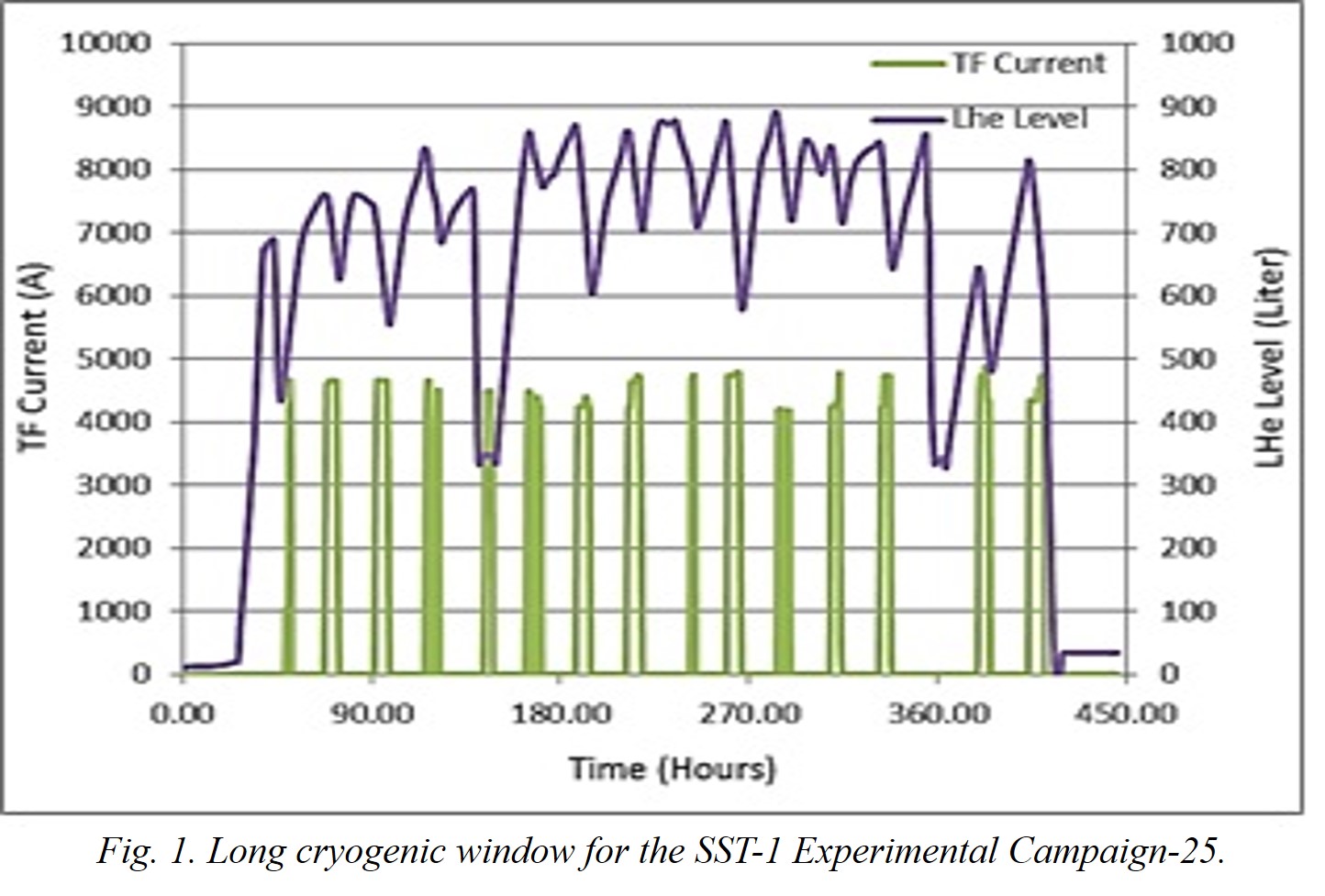
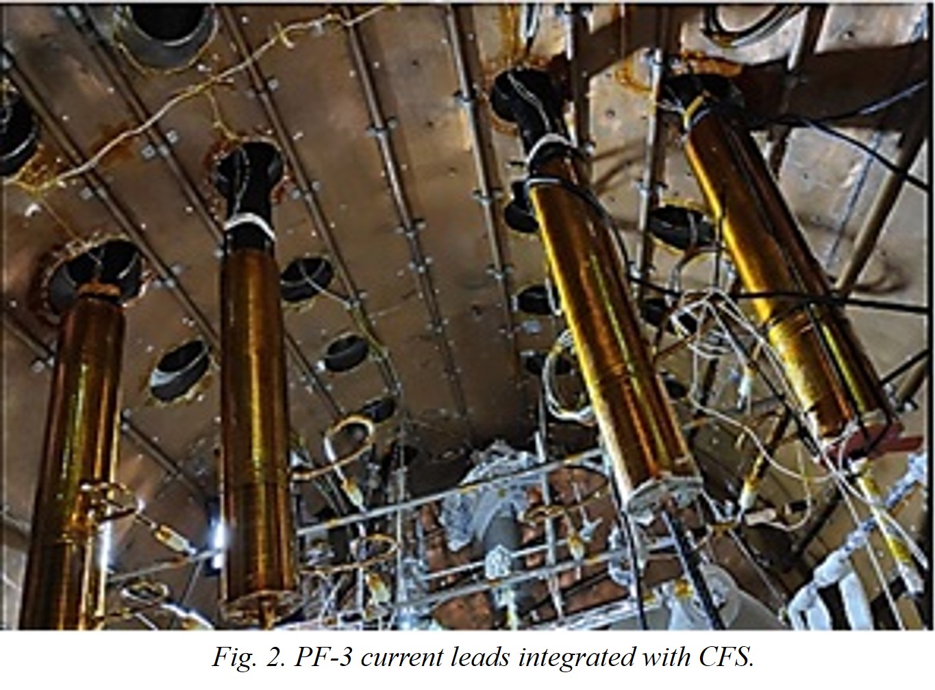
It has been shown that the simultaneous cool down of the TF and PF coils are possible while achieving superconducting transition in all the coils except PF-5 (lower). Cryo heat loads minimization and mitigation within the SST-1 and current feeders system (CFS) to the best possible level, about 100 W at 4.5 K was reduced on to the helium cryogenic system. Efforts on uniform hydraulic distribution achieved while realizing the upgradation of integrated flow distribution and control system. To enhance the reliability and availability of the PLC based automation system, the old Eurotherm PC 3000 PLC system is retrofitted with new Eurotherm T2750 PLC. While adopting the above procedures, we obtained more than 2 weeks of cryogenic stability to charge the TF magnets at 4.7 kA and several hundreds of plasma discharges have been facilitated. After demonstration of longer cryo stable operation along magnet cooling and simultaneously production of ~ 50 l/h of liquid helium (refer Figure 1), we envisaged the possibility to connect the PF-3 current leads to obtain shaped plasma experiments in SST-1. Before installing the PF-3 current leads, electrical safety procedures are required to avoid any kind of Paschen discharge conditions within the PF-3 coils due to reflected voltages arise from the Ohmic coil discharge. For charging PF-3 (Upper/Lower) coils, four current leads are fastened on current feeders system (CFS) providing adequate electrical isolation using G-10 CR intermediate flange and fasteners. Welding of different vacuum breaks and isolators are very critical due to being exposed to high temperature. The electrical insulation is also major challenges on the surface exposed to high voltage (about 3 kV) due to induction. Some surfaces of CLs and feeders are insulated by Kapton tape with GFRP tape while rest of the surfaces will be covered in-situ conditions. The vacuum of cryostat between CFS and SST-1 is isolated to protect the coils and SST-1 from the Paschen-discharge as well as modularity point of view. On helium hydraulics side, pressurized supercritical helium cryogenic circuit will be re-routed and qualified for helium leak tightness. Similarly, liquid helium (LHe) supply lines from main header is re-routed in CFS chamber. All cryogenic circuits will be provided by adequate flexibility by suitable loops, bellows and bends to protect from the undue thermal stresses. Most of the low temperature surfaces (except current leads and feeders) will be covered by superinsulation MLI (Multi-Layer Insulation). Various instrumentation Viz. temperature sensors, voltage taps, pressure drop transducers and flow meters deployed for operational and diagnostics aspects. The PLC and SCADA have been programmed for the real time operation and control of PF-3 current leads. The photograph of PF-3 current leads integration with CFS is shown in Figure 2. The paper, a brief review of the installed cryo sub-systems as well as the plans of simultaneous cool down of the TF and PF coils of SST-1, performance of newly installed PF3 (Top/Bottom) current lead pairs will be discussed.
References
1 Hongyu Bai et al 2002 Construction of a 2 kW/ 4 K helium refrigerator for HT-7U Physics Sciences & Technology Vol 4 No. 3 1305-1310.
2 H.S. Chang, et al 2008 The on-site status of the KSTAR helium refrigeration system AIP Conference Proceedings 985 doi: 10.1063/1.2908582.
[3] L. Serio, ITER Organization, 2007 The ITER Cryogenic System IBF conference 2007, Nice (France).
[4] P.N. Panchal et al 2019 Cryogenic process optimization for simultaneous cool down of the TF and PF superconducting coils of SST-1 Tokamak, ICEC 2019, Oxford, UK.
| Affiliation | Institute for Plasma Research Bhat Gandhinagar India |
|---|---|
| Country or International Organization | India |