Speaker
Description
Introduction
Compass-Upgrade tokamak, which is being constructed in the Institute of Plasma Physics of the Czech Academy of Sciences in Prague, will replace existing Compass tokamak $[1]$. It will be a compact, medium-size ($R=0,89 m, a=0,3 m$), high-magnetic-field ($5 T$) device. The tokamak is expected to operate with plasma densities up to $n_e=10^{21} m^{-3}$. Plasma heating will be performed by $4 \times 1MW$ Neutral Beam Injectors (NBI) with $80 keV$ injection energy. Injectors are grouped by 2 vertically spaced pairs. In the future, heating system will be extended by at least 4 MW Electron Cyclotron Resonant Heating (ECRH) system. At the present design stage, much effort has been devoted to scenario development. NBI system, which is expected to be the main source of plasma heating, demands precise modeling. The high plasma density of Compass-U scenarios is limiting NBI core heating efficiency. To compensate for this effect, the injection tangency radius ($R_t$) can be reduced. On the other hand, more perpendicular injection leads to an increase of the trapped fast ion fraction, which depending on the fast ion deposition, and last closed flux surface (LCFS) position, can cause fast ion orbit losses. Another significant channel of losses can be charge-exchange losses. This research is dedicated to find an optimal geometry of the NBI system using set simulations with the NUBEAM code $[2]$.
Simulation setup
Compass-Upgrade scenarios were developed with the METIS code $[3]$. Magnetic equilibrium geometry was reconstructed by the FIESTA code $[4]$ using METIS output data. Using plasma profiles and magnetic equilibrium from METIS and FIESTA codes, static targets for NUBEAM NBI simulations were created. Three baseline H-mode discharge scenarios ($4MW$ of NBI and $2MW$ of ECRH power) with different toroidal magnetic field strength ($2.5T$,$4.3T$,$5T$) and plasma currents are considered. Each of scenarios was prepared with METIS for various plasma line averaged densities ($1.1\cdot10^{20}-3.2\cdot10^{20}m^{-3}$).
Plasma core heating efficiency
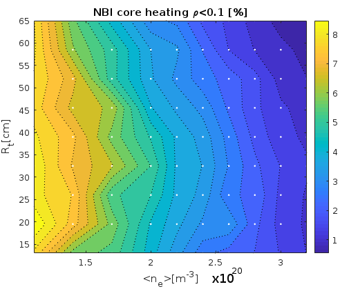
The variation of vertical alignment of NBI injectors in Compass-Upgrade is limited by injectors and port construction. However, the NBI tangency radius can be adjusted up to $65cm$. $R_t$ can be optimized for better plasma core heating performances. Fig.1 shows NBI power fraction that was delivered to both, plasma ions and electrons inside closed flux surface with an index $\rho<0.1$ as a function of $R_t$ and line averaged density for the scenario with $B_t=5T$. In this scenario, high plasma density can be reached. Simulation results show that $80keV$ beam heat deposition is located on the plasma periphery for $R_t=65cm$ when electron densities is higher than $2\cdot10^{20}m^{-3}$. The decrease of $R_t$ improves heat deposition to the plasma core. However very small $R_t$ leads to high trapped particle fraction and reduced number of fast ion trajectories that cross the plasma core. In simulations with densities $n_e>2\cdot 10^{19} m^{-3}$, in order to achieve efficient plasma core heating, injection tangency radius has to be set to around $40cm$.
\section*{NBI power losses}
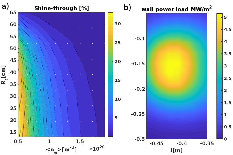
In a case of small electron density, some of the injected beam neutrals can shine through the plasma without ionization. With a low divergence beam of Compass-Upgrade and high NBI power, beam shine-through can cause damage to the first wall. Shine-through losses calculated for scenario with $2.5T$, as it is characterised by a lower densities fig.2(a). With $R_t<40cm$ injection is dangerous in a case of small electron density ($n_e<9\cdot10^{19}$). The first wall shine-through power deposition distribution was calculated using code NUR - Monte-Carlo code (developed by the authors). The code NUR can calculate fast ion deposition and wall shine-through loads using NUBEAM-like beam geometry and fast neutrals stopping rates presented by S. Suzuki $[5]$. Code NUR became a part of a particle following code EBdyna [6]. One can see on the figure Fig.2(b) example of shine-through power distribution on the central column created by a pair of vertically separated injectors. This result was obtained for density of $1.1\cdot10^{-20}m^{-3}$ with $R_t=40cm$. Shine-though, in this case, is equal to $2.4\%$ of NBI power.
In the case of perpendicular injection, most of the fast ions (more than $80\%$) are trapped on banana orbits. However, even in this case, fast ions are well confined and orbit losses are very small for simulated baseline scenarios ($<1\%$). High fraction of trapped ions, in this case, can lead to large ripple losses (not included into the simulation). It was found that orbit losses increases when the plasma is closer to the first outer wall. To investigate this, simulations were repeated using different magnetic equilibrium with the increased plasma minor radius (from $26.8cm$ to $28cm$). As the result, the orbit losses reaching up to $11\%$ of total NBI power in a case of perpendicular injection $R_t=0cm$, and relatively high plasma density $2\cdot 10^{20}m^{-3}$.
In the presence of background neutrals, charge-exchange losses can decrease NBI heating efficiency. Charge-exchange losses increase with fast ion slowing down time, which is usually higher in a case of low electron density. The neutral density profile for the NUBEAM simulations was obtained by METIS code. The result of simulations show that charge-exchange losses reaching values up to $10\%$ of injected power in a case of low-density plasmas ($n_e<8\cdot 10^{19}m^{-3}$). These results can describe general charge-exchange losses behavior, but for quantitative modeling, better simulation model of background neutrals has to be used.
Conclusions
NUBEAM code was adopted to work with METIS and FIESTA codes output data, and predictive modelling of NBI heating on Compass-Upgrade tokamak has been performed. The simulations has shown good confinement of NBI fast ions in most cases. However, during injection with $65cm$ tangency radius in high-density plasmas the core heating is not efficient. The reduction of the injection tangency radius improves plasma core heating efficiency. But on the other hand, it increases the fraction of trapped fast ions. In the case of a smaller magnetic field (scenario with $B_t=2.5T$) when LCFS is close to the plasma wall it leads to the orbit losses that can reach $11\%$ from injected NBI power. High trapped ion fraction could also cause strong ripple losses. Based on our results we can conclude that in the first stages of the tokamak operation, when scenarios with a high magnetic field and densities will not be performed, the optimal NBI injection radius is equal to $65cm$. Setting $R_t$ this way will allow to use NBI for smaller plasma densities without possible wall damage by shine-trough neutrals. On the later operation phase, in order to improve core heating efficiency, NBI has to be performed at $R_t=40cm$. Injections at $R_t<30$ are becoming ineffective at the low-density plasmas due to shine-trough and charge-exchange losses.
References
$[1]$ Panek, R. et al.Fusion Eng. Des.123, 11, DOI: https://doi.org/10.1016/j.fusengdes.2017.03.002 (2017)
$[2]$ Pankin, A. et al.Comput. Phys. Commun.159 Issue 3, 157, DOI: https://doi.org/10.1016/j.cpc.2003.11.002 (2004)
$[3]$ Artaud, J. et al.Nucl. Fusion58, 105001, DOI: https://doi.org/10.1016/j.fusengdes.2017.03.002 (2018)
$[4]$ Cunningham, G. et al.Fusion Eng. Des.88 Issue 12, 3238, DOI: https://doi.org/10.1016/j.fusengdes.2013.10.001 (2013)
$[5]$ Suzuki, S. et al.Plasma Phys. Control. Fusion40, 2097, DOI: https://doi.org/10.1088/0741-3335/40/12/009 (1998)
$[6]$ Jaulmes, F. et al.Nucl. Fusion54, 104013, DOI: https://doi.org/10.1088/0029-5515/54/10/104013 (2014)
| Affiliation | Institute of Plasma Physics of the Czech Academy of Sciences, Prague, Czech Republic |
|---|---|
| Country or International Organization | Czech Republic |