Speaker
Description
The steady-state superconducting tokamak (SST1) [ref1], having major and minor radius of 1.1m and 0.2 m respectively, equipped with a Copper-based central solenoid to provide the required loop voltage. Like in other superconducting tokamaks [ref2-3], SST1 tokamak also relies on ECR breakdown technique to form Ohmic plasmas. Plasma preionization and current start-up is assisted by the 42 GHz ECR system and the LHCD system [ref4-5] is used for driving plasma current non-inductively to achieve continuous wave (CW) discharges. In SST-1, loop voltage amplitude is not only smoothen out inside the vessel but also, delayed by ~12ms due to the continuous vacuum vessel. Moreover, the equilibrium field is provided by a pair of Vertical field coils located outside of cryostat that required a perfect feed-forward current profile and hence, poses challenges for having repeatable Ohmic breakdown. With recent modifications in the magnetic null field configuration [ref6], good repeatable Ohmic plasma discharges could be produced with narrow EC pulse (~50ms) and that allowed in carrying out LHCD current drive experiments on SST1 machine.


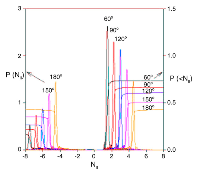
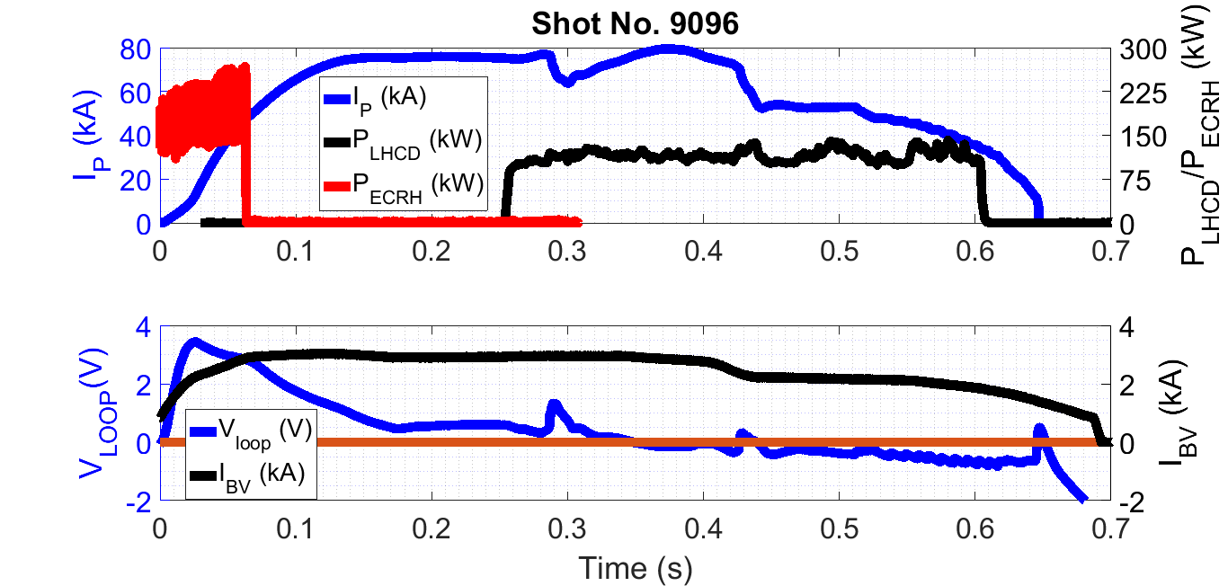
The schematic of the major configuration of the machine is displayed in Figure-1. The direction of the toroidal magnetic field is in anti-clockwise direction and the plasma current is also driven in the same direction by flowing current in Ohmic transformer in anti-clockwise direction. The current in the vertical field coils is driven in clockwise direction to provide equilibrium to the plasma. In order to drive plasma current non-inductively using lower hybrid waves (LHW’s) in the same direction as of plasma current, the grill launches LHW’s in clockwise direction so that momentum from the waves is transferred to the resonant electrons through collisionless Landau damping mechanism. To launch LHW’s in the clockwise direction, the grill is phased from left to right. LHCD system for SST1 machine comprises of klystrons, each rated for 0.5MW-CW rf power at a frequency of 3.7 GHz. The grill antenna having two rows, each row accommodating 32 waveguide elements, is placed 3mm behind the limiter. As the periodicity of the grill antenna is 9mm, it launches waves having parallel refractive index (N//) centered at 2.25 when the adjacent waveguide elements are relatively phased at 90^o. Each waveguide elements are connected to adjustable phase-shifters which provides flexibility in launching the waves with desired N//. The spectrum with different phasing of the grill antenna is shown in figure-2. In the experiments, the phasing of the grill antenna is varied from 90^o to 130^o to launch LH waves with N// centered at 2.25 to 3.25. The toroidal magnetic field is kept at 1.5 T and plasma is formed with plasma current up to ~75kA at [0.9 – 2] x 10-5 mbar pressure of hydrogen gas. Up to ~200 kW of LH power is injected in to the plasma. A typical plasma shot with LH driven plasma current is shown in figure-3. Initially ECR assisted Ohmic discharge is formed and once a stable target plasma at ~75kA is achieved, ~125kW of LH power is injected at ~250 ms. Thereafter, the plasma is maintained with LHW’s up to ~650ms. Figure-3 also shows the temporal evolution of loop voltage and vertical magnetic field. The zero loop voltage current drive indicates complete non-inductive current drive fully supported by LH power. The estimated efficiency of current drive, in worst case, is ~80kA/125kW ~0.67 A/W assuming the entire injected power is absorbed for CD. The line averaged density of similar shots is estimated to be ~[6-8]x10^18 m^{-3} and yields figure of merit for LH current drive as, η_LH = (n_e R_o I)/P= (0.7x〖10〗^191.180)/120 ~ 0.05 x 〖10〗^20 A〖/W/m〗^2.


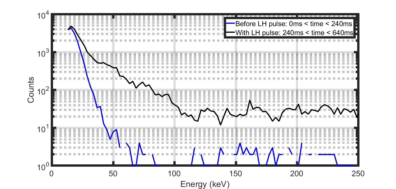
The beneficial effect of suppression of hard x-ray with LH driven current is demonstrated on SST1 machine also as shown in figure-4. The spikes in hard x-rays after LH injection and before ~400ms is attributed to plasma hitting the walls. To further establish that population of suprathermal electrons are generated when injected LH power interacts with tail electrons of the distribution function, the CdTe detectors were employed to measure the photons coming out from plasma lying in the energy range from 20keV to 200 keV. The PHA data shown in figure-5 clearly shows that the counts increases significantly in the presence of LH power and confirms generation of suprathermal electrons when LHW’s interact with tail of the distribution function of the electrons. In experiments with modulated LH power, the entire plasma current could be supported with LH power alone corresponding to nearly zero loop voltage signal with reduced plasma-wall interaction. The effect of modulation could also be observed in 2nd harmonic ECE signals, confirming generation of suprathermal electrons with LH.
References:
[ref1] Saxena, Y. C., SST1 Team, Nucl. Fusion, 40 (6), 1069, 2000.
[ref2] J. Bucalossi et al, Nucl. Fusion, 48 (2008) 054005.
[ref3] Journal of the Korean Physical Society, Vol. 51, No. 4, October 2007, pp. 1313-1319
[ref4] Bora, D., Sharma, P. K., Rao, S. L., Trivedi, R. G., et. al., Fusion Engg. Design, 82, 141, 2007.
[ref5] Sharma, P. K., Ambulkar, K. K., Parmar, P. R., Virani, C. G., et. al., Jour. of Phys. Conf. Series, 208, 012027, 2010.
[ref6] Sharma, P. K., Jain, Y. M., Ambulkar, K. K., Parmar, P. R., et. al., Plasma and Fusion Research, 13, 3502100, 2018.
| Affiliation | Institute for Plasma Research |
|---|---|
| Country or International Organization | India |
