Speaker
Description
Experimental tests on a prototype system of a novel, rapid time-response disruption mitigation system (DMS) being developed as a back-up option for ITER, referred to as the Electromagnetic Particle Injector (EPI) have been able to verify the primary advantages of the concept, which are its ability to meet short warning time scales of <10ms while attaining the projected high velocities for deep radiative payload penetration in ITER-scale plasmas. Because the ITER plasma would have about two-orders of magnitude more energy than in present experiments, realistic 3d MHD simulations, benchmarked against present experiments is an essential step to project to ITER. In support of this requirement, new capabilities have been implemented in the M3D-C1 code to model radiative material injection into tokamak plasmas, and initial simulations for the NSTX-U configuration have been conducted.
Predicting and controlling disruptions is an important and urgent issue for ITER. While a primary focus is the early prediction and avoidance of conditions favorable to a disruption avoidance, some disruptions with a short warning time may be unavoidable. For these cases, a fast time response disruption mitigation method is essential.
Recent studies on DIII-D [Ref. 1] show that the overall response time of the Shattered Pellet Injector (SPI) is 25ms, and because of much larger pellet size and distances, this system is likely to be significantly slower in ITER. Additionally, as the plasma energy content is increased from 0.2MJ to 2MJ, the penetration depth shows a strong reduction [Ref. 1]. ITER, with 350MJ stored plasma energy, could benefit from a DMS that has both fast response time and higher-velocity such as from the EPI. Calculations [Ref. 2] suggest that the high-velocity pellets from EPI could penetrate deep into ITER grade plasmas. The present understanding, based on the theoretical work of Konavalov, et al., is that as little as 5g of Be, if it is deposited deep inside the plasma, may be adequate for both thermal quench and runaway electron mitigation in ITER [Ref. 3].
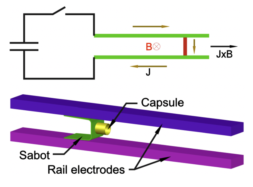
As shown in Fig 1, the EPI relies on an electromagnetic propulsion system to overcome the limitations of present gas-based systems, such as SPI, which are limited to 200m/s for large mass pellets. A metallic sabot is accelerated electromagnetically to the required velocities (> 1km/s) within 2ms, at which point it releases well-defined microspheres, or a shell pellet, of a radiative payload.
Initial experimental tests from the prototype system (EPI-1) have demonstrated 150m/s within 1.5ms, consistent with calculations, giving confidence that larger ITER-scale injector can be developed [Ref. 4]. Following these successful experiments, a new upgraded system, (EPI-2) in a tokamak deployment configuration has been built to increase the velocity to 1km/s. Initial results from the operation of this system at 2.1T have extended the attainable velocities to over 600m/s in the same 1.5ms, consistent with the projections for this system which indicate the attainment of 1km/s with the use of 3T boost magnetic field.
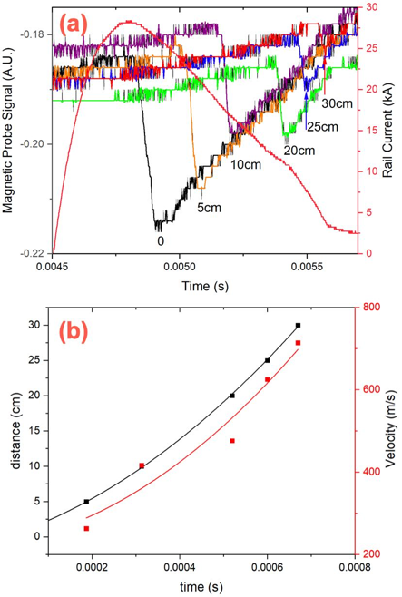
Fig. 2a shows experimental data from the operation of EPI-2. The magnetic field probe traces that record the expanding magnetic flux behind the sabot show continuous acceleration along the 30cm long acceleration region. The processed data from these signals (Fig. 2b) shows the attainment of over 600m/s in about 1ms. Near-term tests plan to extend this velocity to 1km/s by operating the boost coils at 3T. Basic aspects of payload separation from the sabot, and sabot capture have also been demonstrated on EPI-2 at 150m/s, and the method can be extended to over 2km/s.
Unlike the SPI case, the EPI injects a payload consisting of well-defined shape and velocity. Consequently, the 3d MHD modeling of EPI payload penetration should be easier, and more precise, permitting reliable benchmarking against present experiments.
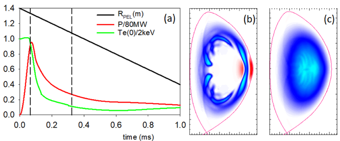
In support of this EPI work, new capabilities have been implemented in the M3D-C1 code. We have implemented a carbon ablation and radiation model into the M3D-C1 code [Ref. 5] and used it to simulate EPI of solid carbon pellets into NSTX-U. (Fig. 3).
The ablation model is based on a neutral gas shielding approach (NGS)[Ref. 6,7] in which the key quantity is the shielding factor which is the ratio of the plasma heat flux that has reached the pellet surface and to the plasma heat flux before entering the pellet neutral cloud.
In the case of strong shielding pellets, an ablation rate equation that is related to the electron temperature, electron density, pellet radius, pellet charge and atomic mass number and the adiabatic index is used. In the weak shielding approximation, the ablation rate is related to the pellet radius, electron density, electron temperature, and the shielding factor and is given in the reference by Kuteev [Ref. 7]. In the intermediate shielding regime, Ref. [6] proposes an interpolation. Both intermediate and weak regimes agree well with a series of AUG shots with C pellets [Ref. 6]. The radiated power is calculated using the KPRAD [Ref. 8] module.
At the very least, it is highly desirable for the DMS to deposit a major portion of the radiative payload inside the q=2 surface in less than the thermal quench duration (~2ms) after the radiative material contacts the plasma edge. In addition, if the radiative payload transit time from the q=2 surface to the magnetic axis is less than the thermal quench duration, then additional advantages, such as the possible suppression of the initiation of runaway electrons becomes possible. The EPI is potentially capable of meeting these important needs for ITER. Because of the well-defined payload velocity and size, the 3d MHD modeling should allow more realistic benchmarking with experimental results from present tokamaks, which is an essential step for reliably projecting disruption mitigation to ITER plasmas.
*This work is supported by U.S. DOE Contracts: DE-AC02-09CH11466, DE-FG02-99ER54519 AM08, and DE-SC0006757.
- R. Raman et al., Nucl. Fusion (2020) https://doi.org/10.1088/1741-4326/ab686f
- R. Lunsford et al., Fusion Science Technol. (2019) DOI: https://doi.org/10.1080/15361055.2019.1629246
- S.V. Konovalov S.V. et al 2012 IAEAFEC 2012 Conf. ITR/ P1-38 (www-naweb.iaea.org/napc/physics/FEC/FEC2012/
papers/338_ITRP138.pdf) - R. Raman et al, Nucl. Fusion 59 (2019) 016021
- N. Ferraro, B. Lyons, C. Kim, et al, Nucl. Fusion 59 016001 (2019)
- Sergeev et al., Plasma Phys. Rep. 32 (2006) 363
- Kuteev et al., Sov. J. Plasma Phys. 10 (1984) 675
- D.G. White, et al, DIII-D Technical Report GA-A22639, General Atomics (1997)
| Affiliation | University of Washington, Seattle, WA, USA |
|---|---|
| Country or International Organization | United States |