Speaker
Description
Introduction
In ITER the density of deuterium and tritium will be controlled by injection of cryogenic pellets, with D and T isotopes separately to allow active isotope ratio control. Due to technical limitations and high pedestal temperatures the pellets will be ablated at the plasma periphery, about at the pedestal top. For deeper penetration one have to invoke curvature drift and inward particle transport. Another parameter governing the ITER pellet fuelling is rather small relative size of the pellets which is difficult to match in medium size machines but just possible by small pellets in JET. This paper present unique pellet fuelling dataset from JET addressing aforementioned issues. As a result for the first time pellets of ITER like relative size are injected into high current high power JET plasmas.
Deuterium pellets into hydrogen plasma
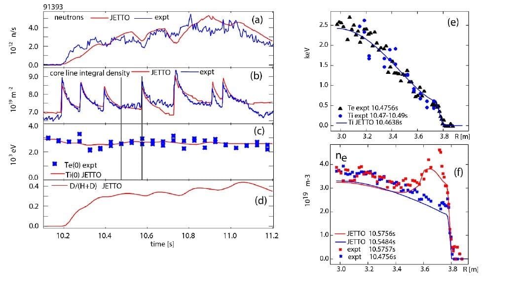
The first experiment [1.] was performed with plasma fuelling provided by hydrogen gas and hydrogen beams. In addition, RF heating at second harmonic hydrogen resonance is used. Plasma current was 1.4MA. After stationary hydrogen H-mode is established, fuelling by ~20mm3 deuterium pellets from the high field side is applied (see figure 1). The reduction from nominal pellet size of 40mm3 was possible by “double cut” method. During injection of deuterium pellets into hydrogen plasma the isotope mix ratio was measured by four independent methods: Balmer-alpha spectroscopy, Penning gauges, charge exchange spectroscopy in the plasma core, and from neutron rate. The last uses the modelling of particle transport JETTO code combined with HPI2 pellet deposition code. All methods show that isotopic mix is close to $n_D/\left(n_H+n_D\right) = 0.45$ during the flattop.
The pellet fuelling flux required for this mix is $\Phi_{pel}=0.045 P_{aux}/T_{e,ped}$ or $\Phi_{pel,D\rightarrow D}=0.10P_{aux}/T_{e,ped}$ to extrapolate to the case of deuterium pellets and deuterium plasma. The front coefficient 0.1 is within a factor 1.4 - 2 the same than found in our previous pellet fuelling experiments in pure deuterium plasmas in AUG [2].
When pellet is injected into plasma it creates transiently a zone of reversed gradient of deuterium density. As a consequence, the deuterium ion particle flux reverses from outwards to inwards and consequently deuterium concentration in the core increases as manifested by increase of neutron rate signal in figure 1. This situation is transient. When evaluated during post pellet phase at $r/a=0.5$ the deuterium particle duffusivity is $D_D=1.38m^2/s$ or $D_D/\chi_{eff}=0.41$.
The neutron rate after the first pellet in figure 1 increases faster than predicted by JETTO Bohm-gyro Bohm model indicating that penetration of deuterium to the plasma core is faster at the beginning of pellet train compared to the later pellet fuelling phase. The gyro-kinetic simulations show that indeed in ion temperature gradient regime the diffusivities for both ion species are higher than the electron diffusivity $D_H \sim D_D>D_e$ [3]. The detailed gyro-kinetic modelling of core particle transport under our condition of isotope mixing by pellets is now ongoing and is subject of separate paper [3].

Hydrogen pellets into deuterium plasma
In second experiment hydrogen pellets are injected into deuterium plasma while the gas fuelling was minimised. The plasma current was set to 1.4MA and 3MA where the low current plasma was aimed to connect to the experiment described above. At 3MA the heating power was ~26 MW. Both pellet sizes, $40mm^3$ and $6mm^3$, are used with 10Hz and 40Hz resp. Under these conditions the mix ratio $n_H/(n_H+n_{D)})\sim 0.4$ is obtained. For each current and pellet size a reference plasma is produced with deuterium pellets into deuterium plasma to complete the dataset, including 3.5MA, high power plasma.
In the above dataset, in particular data with smaller $6mm^3$ pellets are unique as they have the pellet/plasma particle ratio and the ablation depth the same as fuelling pellets in ITER. High temporal resolution interferometry is used to calculate amount of deposited particles during ablation and compared with pellet size from microwave cavity measurement in order to determine injection efficiency. The data indicate high injection efficiency for ablation length $r/a>0.15$ and falling sharply for shallower pellets. The low efficiency for shallower pellets is correlated with prompt ELMs. No difference between hydrogen and deuterium pellets is observed so far. When confirmed these results are important for ITER, in particular that the pellet deposition efficiency is a result of a delicate balance between losses while pellet ablates inside the pedestal and transport of pellet particles beyond the pedestal by curvature drift. Finally note that these observations refer to the time interval during pellet ablation which lasts about 1 ms. After pellet is ablated the behaviour of deposited material is controlled by ELMs, which could be quite complex and will be analysed separately.
Acknowledgements
This work was carried out within the framework of the EUROfusion Consortium and received funding from the Euratom research and training programme 2014–2018 and 2018-2020 under grant agreement No. 633053 and from the RCUK Energy Programme grant No. EP/P012450/1. The views and opinions expressed herein do not necessarily reflect those of the European Commission.
[1.] Valovič M et al Nucl Fusion 59 (2019) 106047
[2] Valovič M et al Plasma Phys. Control. Fusion 60 (2018) 085013
[3] Marin M.et al this conference
| Affiliation | CCFE, Culham Science Centre, Abingdon, OX14 3DB, UK |
|---|---|
| Country or International Organization | United Kingdom |
