Speaker
Description
The high-power helicon antenna has been extensively tested at low power with excellent results, and the full installation in the DIII-D vessel was successfully completed in February 2020, as shown in Fig. 1. High-power striplines feed the antenna from either end (not visible in Fig.1). Commissioning of the 1.2 MW 476 MHz klystron source and associated high voltage power supply and switching network is scheduled to be complete by the end of Spring 2020, enabling the first high-power helicon current-drive experiments in the Summer of 2020. Helicon current drive, or fast wave current drive in the lower hybrid range of frequencies, has long been predicted to be a promising current drive tool for reactor grade plasmas. The system at DIII-D will be the first test of high-power helicon current drive in reactor-relevant plasmas, where full single-pass absorption is expected [a]. Substantial off-axis driven current is predicted for DIII-D (~60 kA/MW).
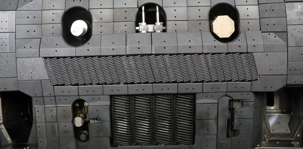
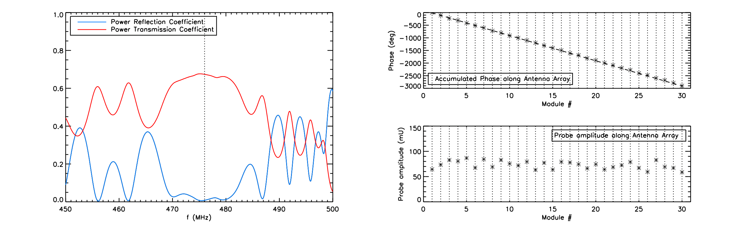
The antenna is a traveling wave antenna of the comb-line type with 30 modules, fed from either side to allow both co and counter current drive. Power is transferred down the antenna through mutual coupling from one module to the next with low losses. All 30 antenna modules were tuned individually to the same resonant frequency to within ±0.5 MHz, and show low losses with a quality factor in excess of 1000. The linear electromagnetic characteristics of the unloaded module array has been extensively tested on the bench and on the DIII-D mock-up wall at instrumentation power levels, with sub-arrays of 10, 15, 20 and 30 modules on curved backplates. The six backplates are coupled capacitively to minimize disruption forces while providing a good RF ground plane. The placement of the modules on the backplates in a 2-module poloidal stagger pattern, which increases the opacity of the Faraday shield to field line penetration, resulted in a periodicity in the mutual coupling between modules that can drive large reflections (~20% power reflected). Adjustment of module placement compensates for this, resulting in a low 1-2% power reflection coefficient and 98.7% power transfer from module to module in air, as shown in Fig. 2 for the 30-module installation in the DIII-D vessel. Also shown in Fig. 2 is data obtained with a pick-up coil in front of the straps just outside the Faraday screen bars. The phase progression and probe amplitude are steady along the length of the array, as expected for a traveling wave antenna.
A 1.2 MW klystron, obtained from SLAC, and the associated high-voltage power pulsing network is being installed and commissioned. The klystron with circulator and dummy load feeds power into a 4-port switching network. The 4-port switch allows feeding of a stripline on either end of the antenna, with the reflected power and the remaining transmitted power each dumped into the dummy load. To satisfy the vessel constraints, the stripline geometry was 3D printed out of Inconel and stainless steel, and copper-coated. The striplines act as a 180-degree phase splitter combined with two 3dB splitters. The four equal-power out-of-phase signals are fed to the coupling straps on the end-modules of the antenna. The antenna and striplines are instrumented with pick-up coils, arc detectors and thermocouples.
Several new and upgraded diagnostics are planned for the helicon program. An edge-density diagnostic will provide density profiles at the antenna. A laser-based technique known as Doppler-free saturation spectroscopy (DFSS) will be implemented to measure the helicon wave electric field vector over a 2D region of space in the edge plasma near the antenna. The wave electric field vector is obtained by fitting the Schrodinger equation to Doppler-free Dβ spectra. This technique results in an accuracy of <5 V/cm, two orders of magnitude greater than that of previous work. For far-field wave measurements, the existing Phase Contrast Imaging (PCI) diagnostic is being upgraded with a heterodyne detection system able to detect fluctuations at 476 MHz. Using values for the wave electric field estimated by full-wave modeling work, it is expected that the PCI will be able to measure the spatial structure of perturbed density with favorable signal-to-noise ratio.
Helicon wave current drive will soon be investigated in high density, high electron beta plasmas where full single-pass absorption is expected – conditions similar to that in steady-state AT burning plasma devices.
This work was supported in part by the US Department of Energy under DE-FC0204ER54698, DE-AC05-00OR22725, DE-FG02-94ER54235, DE-SC0013911 and DE-AC02-09CH11466.
[a] R. I. Pinsker et al, Nuclear Fusion 58, 106007 (2018)
| Affiliation | General Atomics |
|---|---|
| Country or International Organization | United States |